
Project Planning
- Perform a risk assessment of the installation to assess the consequences of flooding due to blockages of silt and scale build up within the pipe system. Repeat this assessment for unexpected hydraulic demands due to accidental spillage, thunderstorms and extraneous events.
- Perform the necessary risk assessment if the system is likely to be subjected to thermal shock. Within design limits, ACO Pipe is particularly tolerant of sudden temperature changes without risk of damage.
- Avoid selecting pipe sizes that are at, or close to, their hydraulic capacities, as the long-term effects of silt and scale can reduce a system’s hydraulic capacity over time.
- For storm water applications, check the geographical location to confirm the design rainfall intensity.
- Confirm the actual gradient of the installed pipe system. A level (or nearly level) gradient will have a reduced hydraulic performance compared to installations with defined gradients.
- Assess the fluids to be drained in the system to avoid corrosion of the pipe and/or seals. Checklist as follows:
– Identify each chemical contained in the fluid.
– Establish chemical concentration(s).
– Confirm maximum temperature of the solution. - Given the above information, the correct seal (see here for more information) can be selected.
- Design the system with the minimum number of joints and limit the number of bends. This will help to reduce both costs and hydraulic losses.
- Provide go/products/installation-fittings/od access points for cleaning/rodding to maintain the hydraulic performance of the system.
- Care should be taken to avoid damage, both during and after installation, as dents and kinks will affect the hydraulic performance. For above ground applications, damage will also affect the system’s aesthetics.
The following standards will assist designers select the correct size of pipe system for a particular application:
- EN 12056: Gravity Drainage Systems Inside Buildings.
- EN 752: Drain and Sewer Systems Outside Buildings.
Pipework Support
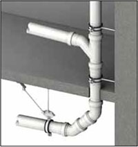 Installation should be in accordance with the manufacturer’s recommendations, EN 12056–2, EN 12056–3 and EN 752.
Designers must ensure that all pipework is supported with brackets according to the requirements of AS/NZ 3500.
ACO Pipe® sockets are fitted with EPDM seals as standard for regular drainage applications. For particularly aggressive applications, FPM and NBR seals are available. Refer to the table below to assess suitability and contact ACO.
EPDM (Ethylene Propylene Diene Monomer)
EPDM was originally developed during the 1950s for vehicle tyre applications. It reached wider applications because of its suitability for outdoor use.
FPM (Fluoroelastomer)
FPM is a fluorocarbon and the best material for resistance to hostile chemical and oil environments at normal and elevated temperatures. This material is widely used in the chemical and pharmaceutical industries, but is significantly more expensive than EPDM.
NBR (Nitrile rubber)
NBR has good water resistance, excellent chemical resistance and durability.
Seal Assembly Replacement or Upgrade
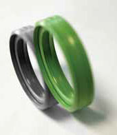 The double lip seal is easily removed and replaced from the female end of all ACO Pipe®, pipes and fittings. This allows easy on-site upgrade of the seal material.
Seal Installation Notes
- If changing the seal, ensure the correct size and grade of seal is selected for the application (see table below).
- Ensure the seal itself and the zone around the pipe and/or fitting receiving the seal is clean, dry and free from dust, grit and any metallic particles.
- Insert the dry seal into the pipe and/or fitting recess. NOTE: the seal MUST be inserted so the double sealing lips face away from the opening of the pipe and/or fitting.
- Do not use tools to aid the assembly process otherwise damage to the pipes, fittings and seals may occur.
| EPDM | FPM | NBR | ||
|---|---|---|---|---|
| Water Resistance | Excellent | Good | Good | |
| Chemical Resistance | Acids Bases | Good Good | Excellent Good | Excellent Good |
| Solvent Resistance (20°C) | Alcohol Acetone Benzene | Good Good Unsatisfactory | Good Unsuitable Good | Good Unsuitable Unsuitable |
| Oil Resistance | ASTM Oil No. 1 @ 20°C ASTM Oil No. 1 @ 100°C ASTM Oil No. 3 @ 20°C ASTM Oil No. 3 @ 100°C | Fair Unsatisfactory Unsatisfactory Unsatisfactory | Excellent 150°C Excellent Excellent 150°C Excellent | Excellent 150°C Good Excellent 150°C Good |
| Fuel Resistance | ASTM Fuel B @ 20°C | Unsatisfactory | Excellent | Excellent |
| Resistances | Oxidation Ozone & Weathering | Excellent Outstanding | Outstanding Outstanding | Outstanding Low |
| Heat Resistance | Maximum Continuous Maximum Intermittent | 130°C 150°C | 205°C 300°C | 80°C 100°C |
| Low Temperature Resistance | – 50°C | – 20°C | – 30°C | |
| Gas Permeability | Fairly Low | Very Low | Very Low | |
| Physical Strength | Good | Good | Good | |
| Compression Set Resistance | Good | Good | Good | |
| Tear & Abrasion Resistance | Good | Good | Good | |
| Cost Factor (1 = low) | 1 | 20 | 2 |
Compared to cast iron, clay and vitreous pipe systems, stainless steel pipes have a considerably smoother bore (Manning Coefficient: 0.011) and in general, are less susceptible to internal scaling.
In some instances, low roughness coefficients (ks) are not generally a true reflection of the long-term hydraulic performance of the installed system. Roughness coefficients of 0.6mm should be used for rainwater/storm drainage and 1.5mm for soil/foul drainage.
Flow Tables
Two sets of flow tables are presented within this design guide.
Table 1 is for pipes installed with level (or nearly level) gradients where the steady, uniform flow equations are not applicable. The data therefore has been generated from ACO’s hydraulic design program ‘Hydro’ that is based on the equations of spatially-varied flow.
Table 2 is for pipes installed with varying gradients. The data is based on the Colebrook-White equation using an appropriate roughness coefficient for stainless steel.
When draining storm or foul water, it is inevitable that sediment deposits will occur within the drainage system.
Sediment and scale deposits will reduce the flow rate through any pipe system and it is recommended that an allowance is made for this within the design and planning phase.

Flow rates based on Colebrook-White formula.
Roughness coefficient ks = 0.6 mm
| Gradient | Pipe ø 50 mm | Pipe ø 75 mm | Pipe ø 110 mm | Pipe ø 125 mm | ||||
|---|---|---|---|---|---|---|---|---|
| [%] | Flow rate Q [l/s] |
Velocity v [m/s] |
Flow rate Q [l/s] |
Velocity v [m/s] |
Flow rate Q [l/s] |
Velocity v [m/s] |
Flow rate Q [l/s] |
Velocity v [m/s] |
| 10.0 | 2.74 | 1.52 | 8.40 | 2.01 | 23.81 | 2.60 | 33.61 | 2.83 |
| 7.5 | 2.38 | 1.31 | 7.28 | 1.74 | 20.62 | 2.25 | 29.11 | 2.45 |
| 5.0 | 1.94 | 1.07 | 5.94 | 1.42 | 16.83 | 1.84 | 23.77 | 2.00 |
| 4.5 | 1.84 | 1.02 | 5.64 | 1.35 | 15.97 | 1.74 | 22.55 | 1.90 |
| 4.0 | 1.73 | 0.96 | 5.31 | 1.27 | 15.06 | 1.64 | 21.26 | 1.79 |
| 3.5 | 1.62 | 0.90 | 4.97 | 1.19 | 14.08 | 1.54 | 19.88 | 1.67 |
| 3.0 | 1.50 | 0.83 | 4.60 | 1.10 | 13.04 | 1.42 | 18.41 | 1.55 |
| 2.5 | 1.37 | 0.76 | 4.20 | 1.00 | 11.90 | 1.30 | 16.80 | 1.41 |
| 2.0 | 1.23 | 0.68 | 3.76 | 0.90 | 10.64 | 1.16 | 15.03 | 1.26 |
| 1.5 | 1.06 | 0.59 | 3.25 | 0.78 | 9.22 | 1.01 | 13.01 | 1.10 |
| 1.0 | 0.87 | 0.48 | 2.66 | 0.63 | 7.53 | 0.82 | 10.63 | 0.89 |
| Gradient | Pipe ø 160 mm | Pipe ø 200 mm | Pipe ø 250 mm | Pipe ø 315mm | ||||
|---|---|---|---|---|---|---|---|---|
| [%] | Flow rate Q [l/s] |
Velocity v [m/s] |
Flow rate Q [l/s] |
Velocity v [m/s] |
Flow rate Q [l/s] |
Velocity v [m/s] |
Flow rate Q [l/s] |
Velocity v [m/s] |
| 10.0 | 64.15 | 3.31 | 116.89 | 3.83 | 218.31 | 4.45 | 401.51 | 5.15 |
| 7.5 | 55.56 | 2.87 | 101.22 | 3.32 | 188.95 | 3.85 | 347.54 | 4.46 |
| 5.0 | 45.36 | 2.34 | 82.65 | 2.71 | 154.13 | 3.14 | 283.52 | 3.64 |
| 4.5 | 43.03 | 2.22 | 78.40 | 2.57 | 146.17 | 2.98 | 268.90 | 3.45 |
| 4.0 | 40.57 | 2.10 | 73.92 | 2.43 | 137.77 | 2.81 | 253.45 | 3.25 |
| 3.5 | 37.95 | 1.96 | 69.14 | 2.27 | 128.82 | 2.63 | 236.99 | 3.04 |
| 3.0 | 35.13 | 1.81 | 64.01 | 2.10 | 119.20 | 2.43 | 219.31 | 2.82 |
| 2.5 | 32.07 | 1.66 | 58.43 | 1.92 | 108.74 | 2.22 | 200.09 | 2.57 |
| 2.0 | 28.68 | 1.48 | 52.26 | 1.71 | 97.18 | 1.98 | 178.83 | 2.30 |
| 1.5 | 24.84 | 1.28 | 45.26 | 1.48 | 84.05 | 1.71 | 154.70 | 1.99 |
| 1.0 | 20.28 | 1.05 | 36.95 | 1.21 | 68.48 | 1.40 | 126.07 | 1.62 |
Note: The flow rates shown above assume an unrestricted discharge from the pipe. For installations without an unrestricted discharge, the flow rate will be affected by the downstream throttle.
- For shallow gradients, the Colebrook-White formula underestimates flow rates (because when gradient tends towards zero %, velocity also tends to zero).
- For level or nearly level installations (slope < 1 %), spatially varied flow tables should be used.
Stainless steel resistance table
The corrosion resistance information contained within this table is indicative only.
All data is based on reactions noted at an ambient temperature of 20°C. Higher temperatures will generally reduce the corrosion resistance of the materials.
Typical factors that affect material selection:
- type(s) of chemical(s) and % composition in the liquid
- concentration percentages
- contact time with trough system
- temperatures of liquid flowing into the trough
- flushing system employed o clear liquids from the system
- type of cleaning agent (see Care & Maintenance)
- grate, locking mechanism and trash basket materials
- sealant for compatibility, if applicable
Test samples should be used for final determination of chemical resistance, contact ACO.
| Recommended | |
| Suitable, contact ACO for further advice | |
| Not recommended | |
| No data available |
| Reagent | Stainless Steel 304 | Stainless Steel 316 |
|---|---|---|
| Acetic Acid 20% | ||
| Acetic Acid 80% | ||
| Acetone | ||
| Alcohol (Methyl or Ethyl) | ||
| Aluminium Chloride | ||
| Aluminium Sulphate | ||
| Ammonia Gas (Dry) | ||
| Ammonium Chloride | ||
| Ammonium Hydroxide | ||
| Ammonium Nitrate | ||
| Ammonium Phosphate | ||
| Ammonium Sulphate | ||
| Ammonium Sulphide | ||
| Amyl Chloride | ||
| Aniline | ||
| Barium Chloride | ||
| Barium Hydroxide 10% | ||
| Barium Sulphate | ||
| Barium Sulphide | ||
| Beer | ||
| Beet Sugar Liquors | ||
| Benzene | ||
| Benzoic Acid | ||
| Bleach -12.5%Active C1 | ||
| Boric Acid | ||
| Bromic Acid | ||
| Bromine Water | ||
| Butane | ||
| Calcium Carbonate | ||
| Calcium Chloride | ||
| Calcium Hydroxide | ||
| Calcium Hypochlorite | ||
| Calcium Sulphate | ||
| Cane Sugar Liquors | ||
| Carbon Acid | ||
| Carbon Bisulphide | ||
| Carbon Dioxide | ||
| Carbon Monoxide | ||
| Carbon Tetrachloride | ||
| Caustic Potash | ||
| Caustic Soda | ||
| Chloride (Dry) | ||
| Chloride (Wet) | ||
| Chloroacetic Acid | ||
| Chlorobenzene | ||
| Chloroform | ||
| Chrome Acid 50% | ||
| Chromic Acid 10% | ||
| Citric Acid | ||
| Copper Chloride | ||
| Copper Cyanide | ||
| Copper Nitrate | ||
| Copper Sulphate | ||
| Cottonseed Oil | ||
| Cresol | ||
| Cyclohexanone | ||
| Cyclorexanol | ||
| Dimethyleanine | ||
| Dionylphalate | ||
| Disodium Phosphate | ||
| Distilled Water | ||
| Ethyl Acetate | ||
| Ethylene Chloride | ||
| Ethylene Glycol | ||
| Ethylene Glycol | ||
| Ferric Sulphate | ||
| Fluorene Gas (Wet) | ||
| Formaldehyde (37%) | ||
| Formic Acid (90%) | ||
| Freon 12 | ||
| Fruit Juices and Pulp | ||
| Furfural | ||
| Gasoline (Refined) | ||
| Glucose | ||
| Glycerine | ||
| Hydrobromic Acid (20%) | ||
| Hydrochloric Acid (40%) | ||
| Hydrocyanic Acid | ||
| Hydrogen Peroxide (90%) | ||
| Hydroquinone | ||
| Hypochlorous Acid | ||
| Iodine | ||
| Kerosene | ||
| Lactic Acid 25% | ||
| Linseed Oil | ||
| Liqueurs | ||
| Magnesium Chloride | ||
| Magnesium Sulphate | ||
| Maleic Acid | ||
| Methyl Chloride | ||
| Methyl Ethyl Ketone | ||
| Milk | ||
| Minerals Oils | ||
| Muriatic Acid | ||
| Nickel Chloride | ||
| Nickel Sulphate | ||
| Oils and Fats | ||
| Oleic Acid | ||
| Oleum | ||
| Oxalic Acid | ||
| Palmitic Acid 10% | ||
| Perchloric Acid 10% | ||
| Perchloric Acid 70% | ||
| Petroleum Oils (Sour) | ||
| Phenol 5% | ||
| Phosphorous Trichloride | ||
| Photographic Solutions | ||
| Picric Acid | ||
| Plating Solutions | ||
| Potassium Carbonate | ||
| Potassium Chloride | ||
| Potassium Cyanide | ||
| Potassium Dichromate | ||
| Potassium Hydroxide | ||
| Potassium Permanganate | ||
| Potassium Sulphate | ||
| Propane Gas | ||
| Propyl Alcohol | ||
| Sea Water | ||
| Sewage | ||
| Silver Nitrate | ||
| Silver Sulphate | ||
| Sodium Bicarbonate | ||
| Sodium Bisulphite | ||
| Sodium Carbonate | ||
| Sodium Cyanide | ||
| Sodium Ferrocyanide | ||
| Sodium Hydroxide | ||
| Sodium Hypochlorite | ||
| Sodium Sulphate | ||
| Sodium Sulphide | ||
| Sodium Sulphite | ||
| Sodium Thiosulphate | ||
| Stannous Chloride | ||
| Stearic Acid | ||
| Sulphite Liquor | ||
| Sulphurous Acid | ||
| Sulphur | ||
| Sulphur Dioxide (Dry) | ||
| Sulphur Dioxide (Wet) | ||
| Sulphuric Acid 50% | ||
| Sulphuric Acid 70% | ||
| Sulphuric Acid 93% | ||
| Tannic Acid | ||
| Tanning Liquors | ||
| Tartaric Acid | ||
| Toluene | ||
| Trichloroethylene | ||
| Triethanolamine | ||
| Trisodium Phosphate | ||
| Turpentine | ||
| Urea | ||
| Urine | ||
| Vinegar | ||
| Water (Fresh) | ||
| Water (Mine) | ||
| Water (Salt) | ||
| Whisky | ||
| Wines | ||
| Xylene | ||
| Zinc Chloride | ||
| Zinc Sulphate |
Stainless steel and nitrile rubber are easy to clean. Washing with soap or a mild detergent and warm water, followed by a clean water rinse is usually adequate for most industrial applications. An enhanced aesthetic appearance will be achieved if the cleaned surface is finally wiped dry.
Acids should only be used for on-site cleaning when all other methods have been proved unsatisfactory. Rubber gloves should be used and care taken to ensure acid cleaners are not spilt over adjacent areas.
Special precautions are necessary with oxalic acid and solvents should not be used in closed spaces without adequate ventilation. Manufacturer’s directions should always be followed.
If the suggestions in the table below have been attempted and the result is still unsatisfactory, stainless steel is able to be mechanically cleaned by specialists on site. Please contact ACO for further information.
| Problem | Cleaning agent | Comment |
|---|---|---|
| Routine cleaning, all finishes. | Soap or mild detergent and water (such as dishwashing liquid). | Sponge, rinse with clean water, wipe dry if necessary. |
| Fingerprints, all finishes. | Soap or warm water or organic solvent (e.g. acetone, alcohol). | Rinse with clean water, wipe dry if necessary. |
| Stubborn stains and discolouration. | Mild cleaning solutions or cream cleanser. | Rinse well with clean water and wipe dry. |
| Oil and grease marks, all finishes. | Organic solvents (e.g. acetone, alcohol). | Clean after soap and water, rinse with cleanwater and dry. |
| Rust and other corrosion products. | Oxalic acid. | Rinse well with clean water. The cleaning solution should be applied with a swab and allowed to stand for 15–20 minutes before being washed away with water. Use a mild cleaning solution to give a final clean if required. |
| Scratches on brush (satin) finish. | Household synthetic fibre scouring pads. | Do not use ordinary steel wool, as particles can become embedded in stainless steel and cause surface problems. For deeper scratches; apply scourer in direction of polising. Clean with soap or detergent as per routine cleaning. |